Surveying is a process of determining or identifying different features of a land area. It helps in planning or mapping an area. Drone survey has increasingly become popular, and it is obvious so, because of its unparalleled match when it comes to accuracy, speed, cost, etc.
The workflow of drone survey is also very easy to understand. The drone flies and captures the photos of the land and returns. A user must upload photos on photogrammetry platforms likeSurveyaan Geoworkspace, etc., the software takes it’s time to stitch all photos together and then generates valuable results such as Orthomosaic, Digital Surface Model (DSM), Digital Terrain Model (DTM), 3D Point Cloud and 3D Model. These results can be imported in software like QGIS, AutoCAD.
In this article, we will learn to import Orthomosaic in AutoCAD. Before moving further, just wanted to let you guys know that the content has been posted in video format on our YouTube channel SurveGyaan by Surveyaan.
An orthomosaic, or orthophoto or orthomap, is an accurate representation of the Earth’s surface. The aerial photos are stitched together and processed to form a single map which is known as Orthomosaic. So, to import Orthomosaic into AutoCAD, we need to have one.
Import Orthomosaic
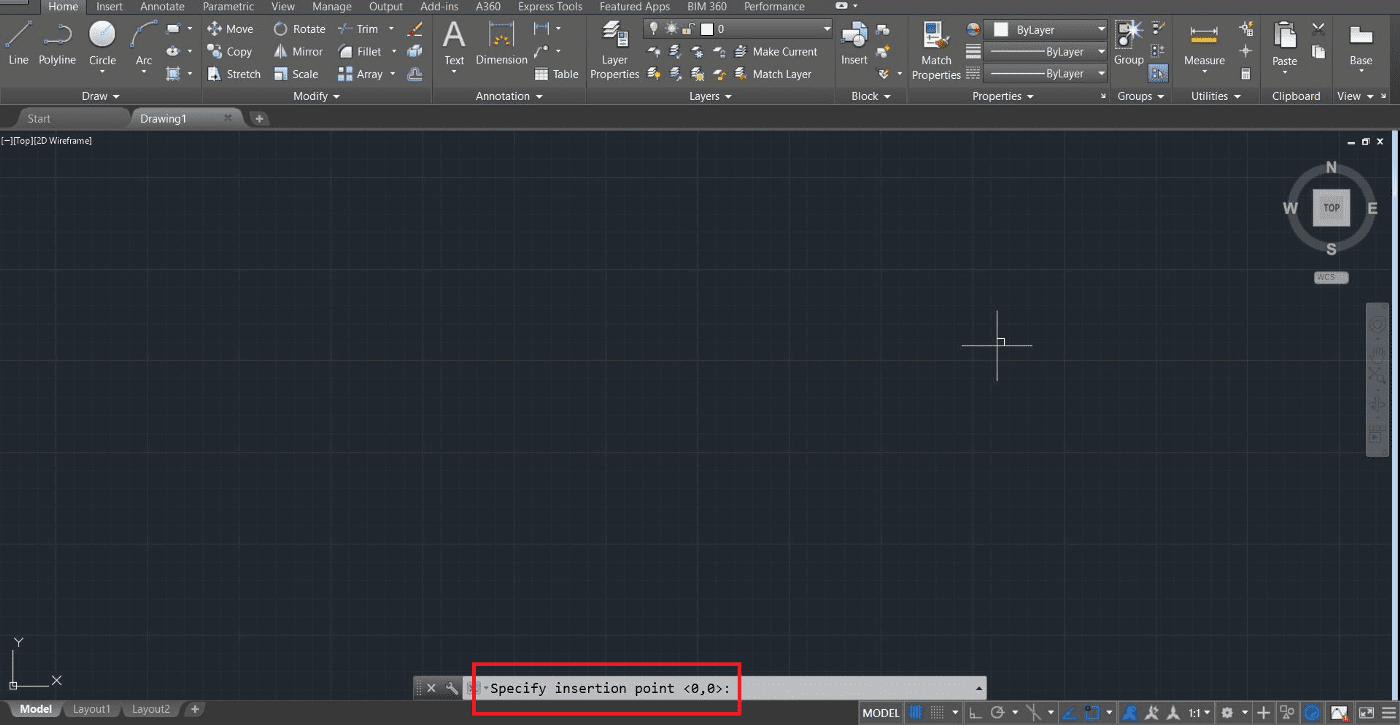
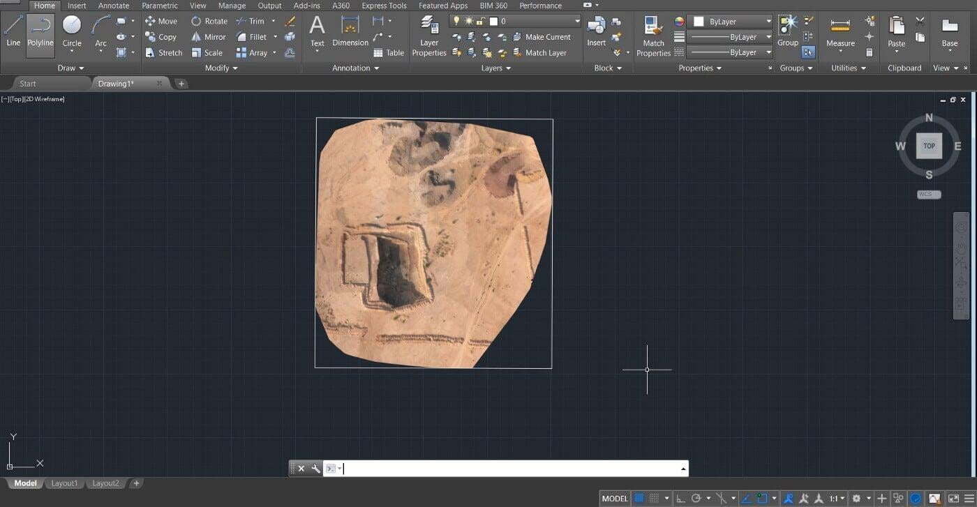
Open AutoCAD and start a new drawing. Simply drag the orthophoto into AutoCAD. It asks for few things as mentioned below:
Insertion points at origin
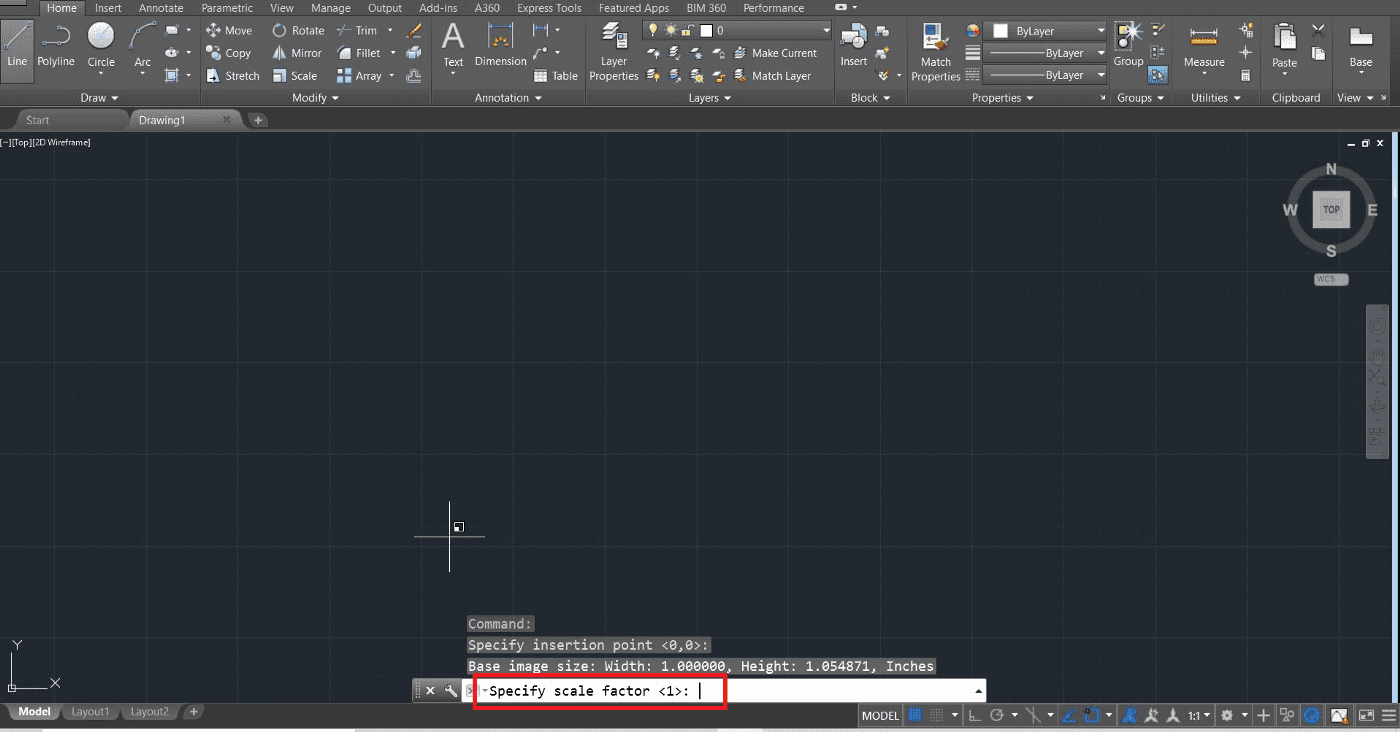
Scale Factor: By default, value is 1 and we can keep the same by pressing Enter key.
Rotation Angle around Origin: We can keep the default value again by pressing Enter key.
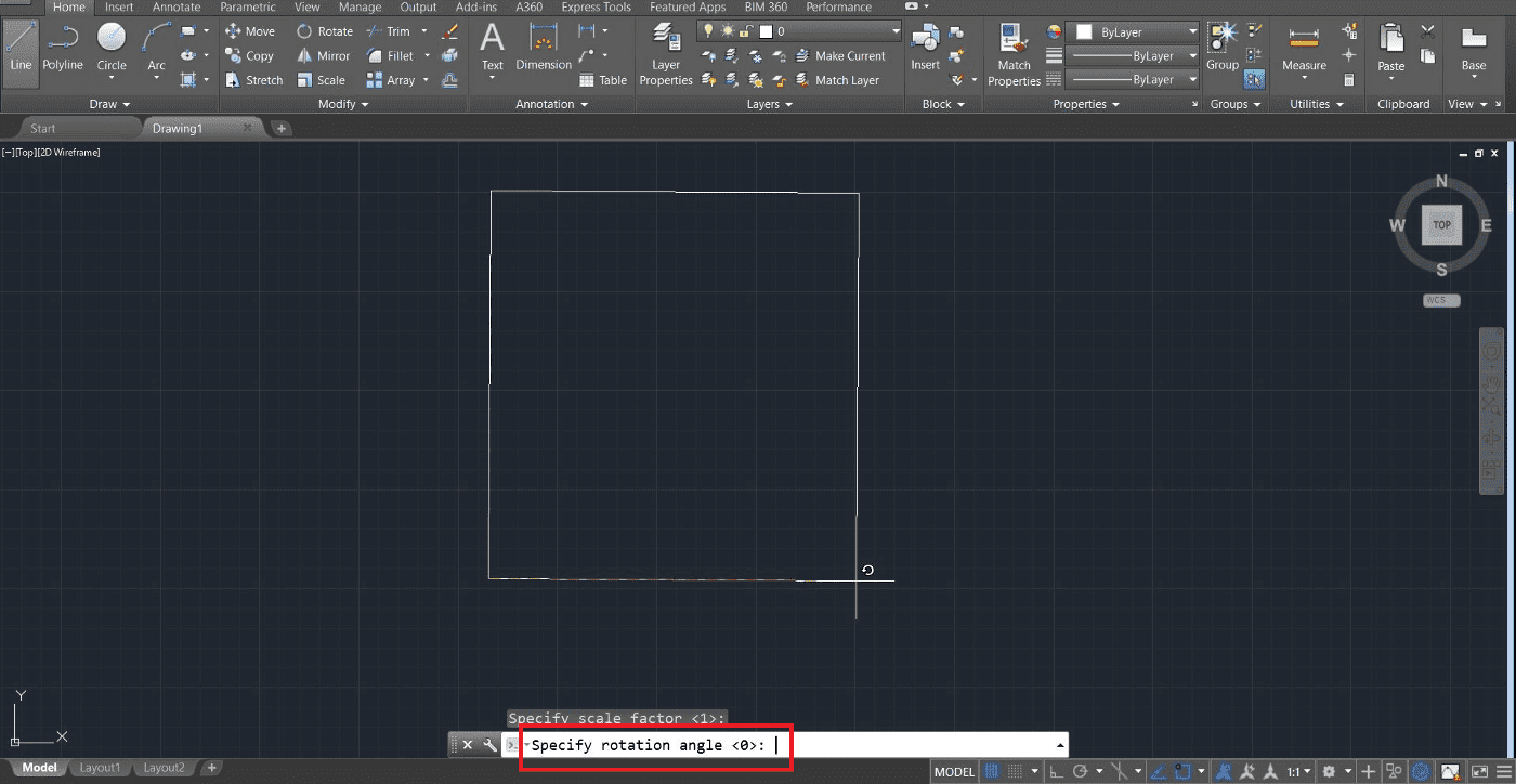
Congratulations. The orthomosaic is imported.
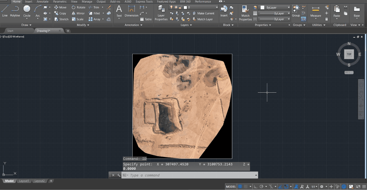
The orthomosaic imported does not contain its original world coordinates. If you type ID command, you will get X and Y coordinates of simple image relative to Origin. To display the original world coordinates, we need to install a tool named, GeoRefImg.
Install GeoRefImg Tool
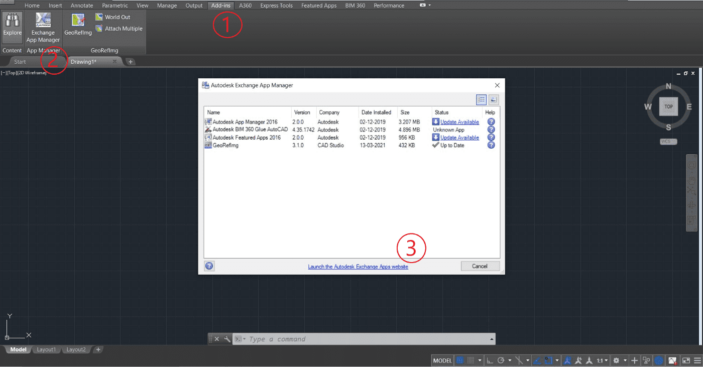
Click on Add-ins (1) menu and select Exchange App Manager (2). Click on Launch the Autodesk Exchange Apps Website (3).
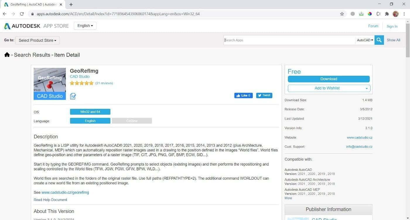
Search for GeoRefImg tool in the search bar. To download, you need to provide credentials and then install it with the default settings.
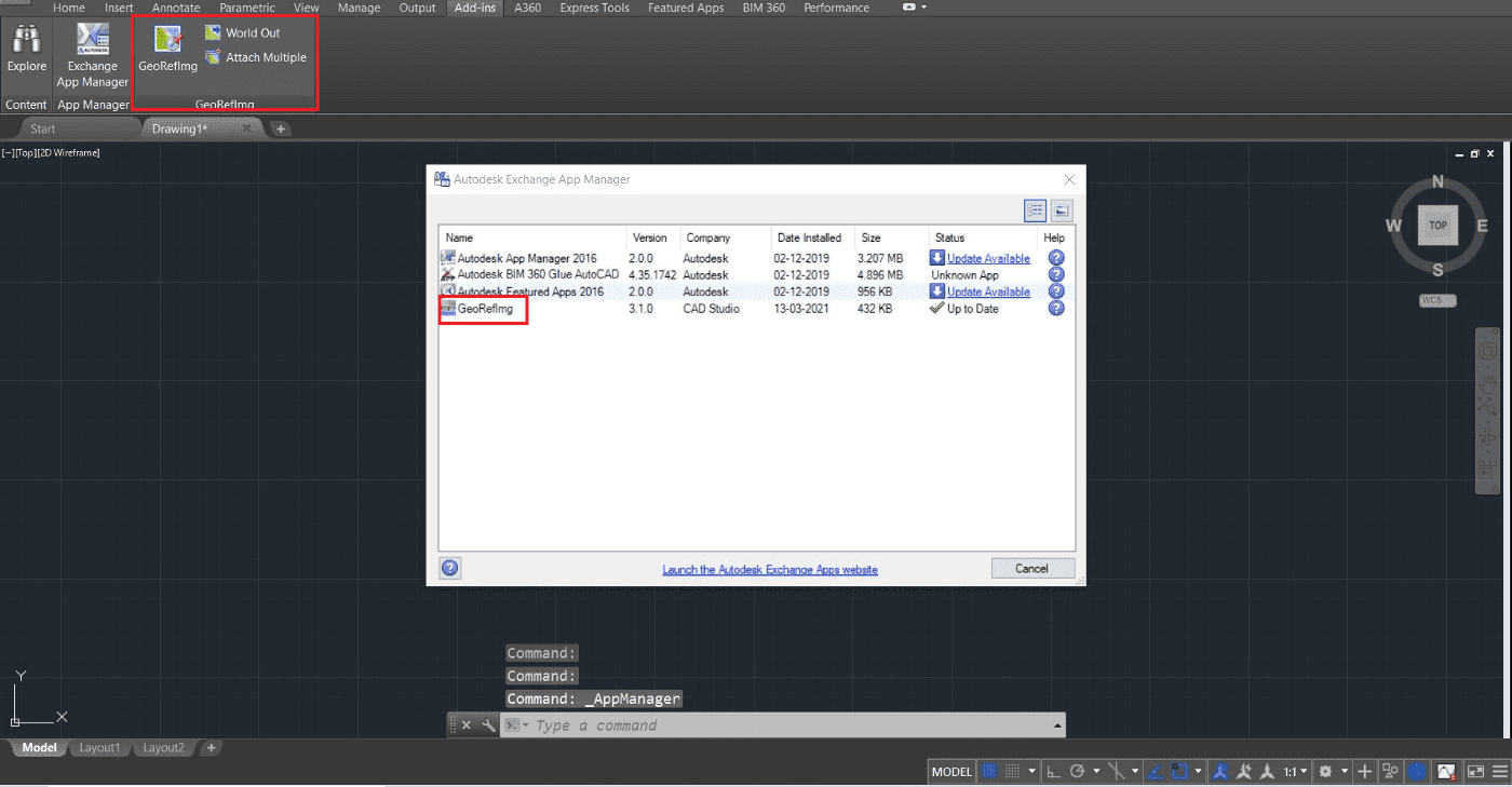
Once installed, you can verify by typing GEOEFIMG in the command or you view the same by clicking on Add-Ins again as shown below.
Import World file
Make sure to have World file. Keep the file in the same location as that of Orthophoto with the same name.
Make sure to have World file. Keep the file in the same location as that of Orthophoto with the same name.
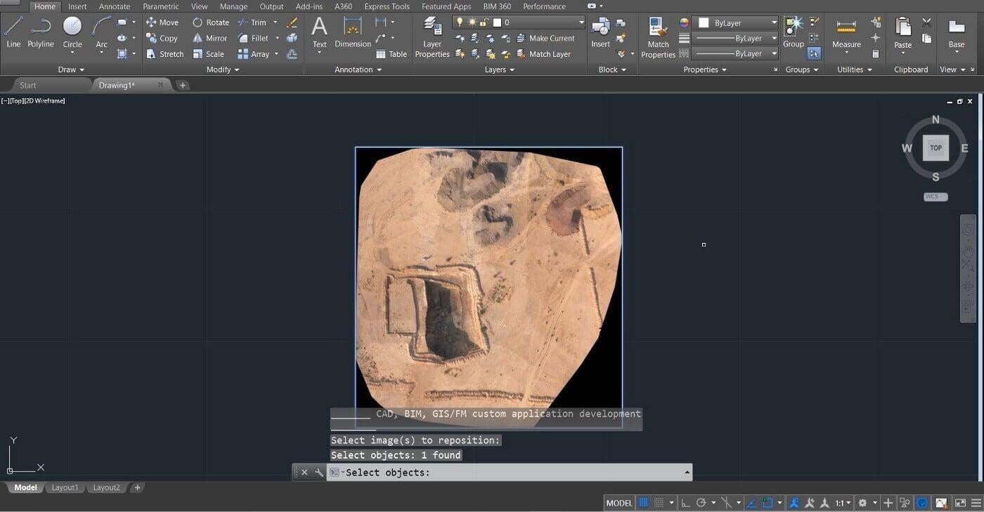
Type GEOREFIMG command and select any of the corner points of the map
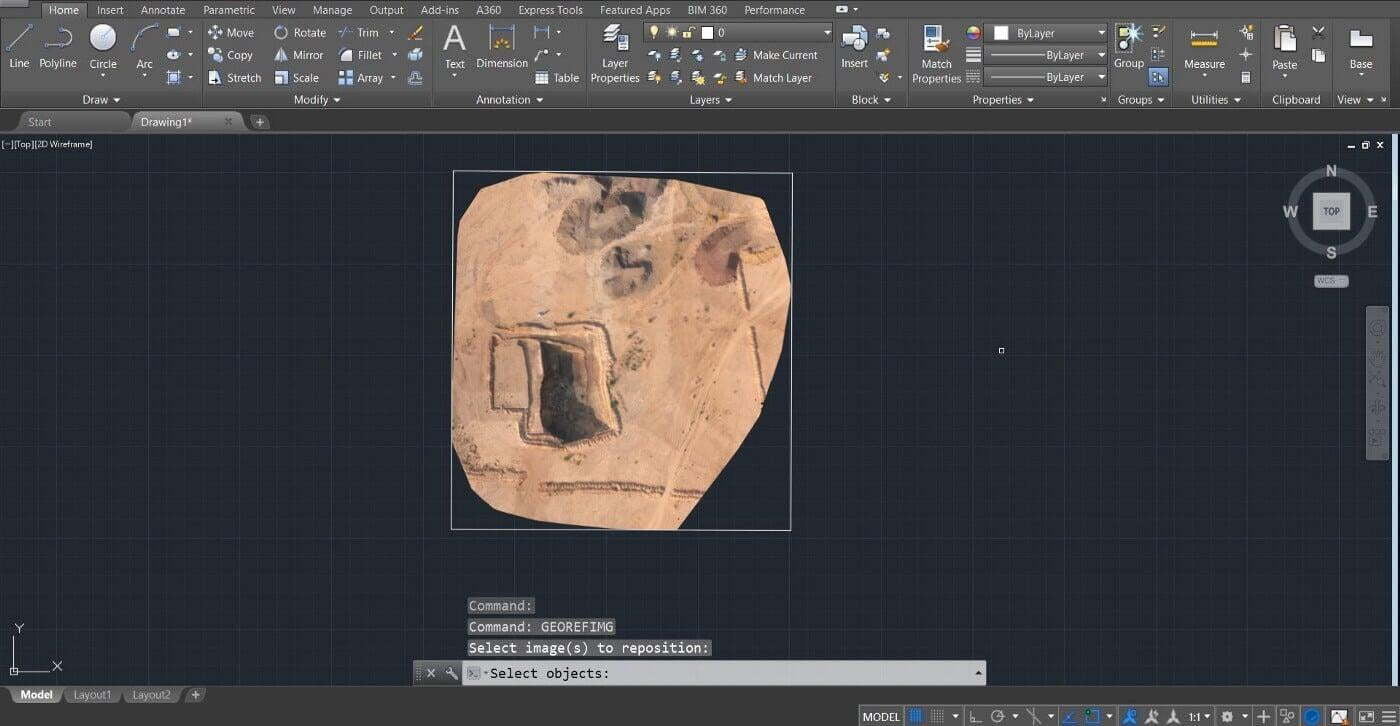
Once selected, it highlights the map by blue and then press Enter.
Calculations
Coordinates: To view the world coordinates, type again ID command and click anywhere on the map.
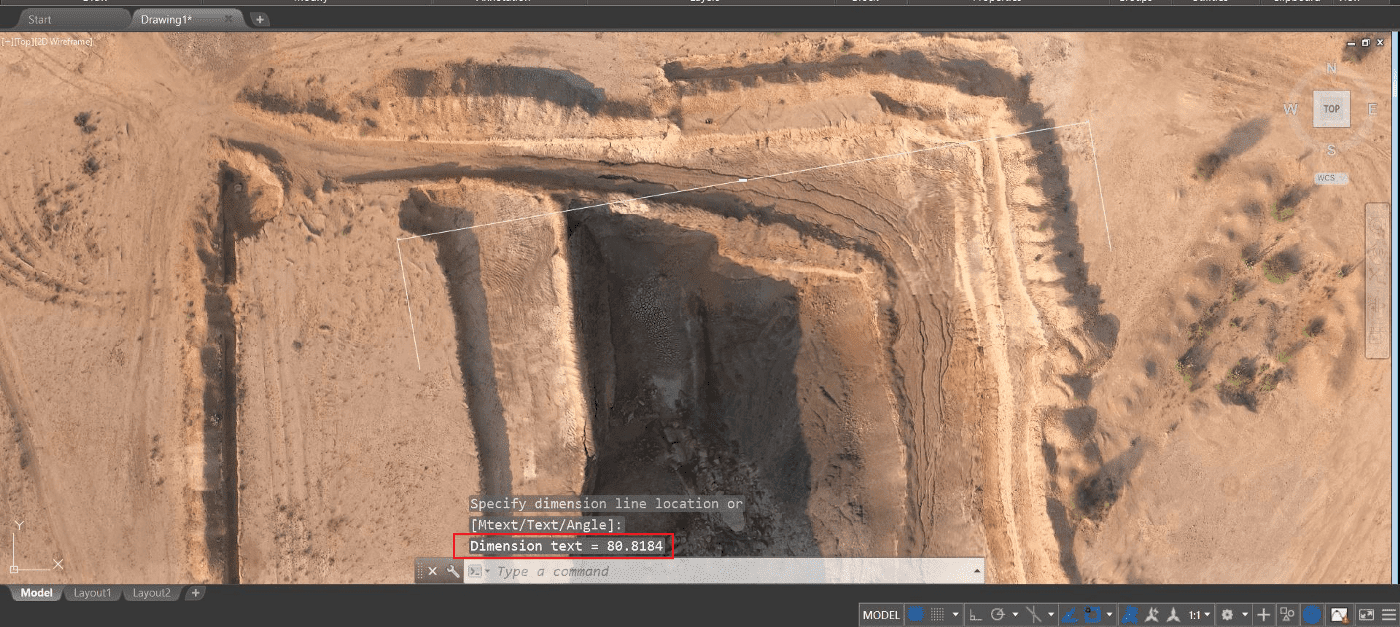
Distance: Type DAL command and select two points to measure distance between them. The highlighted text shows the distance between two points and its unit is in meters.
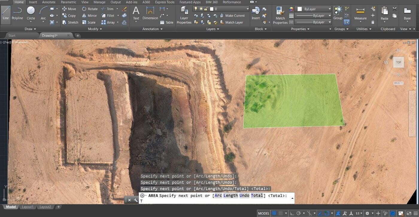
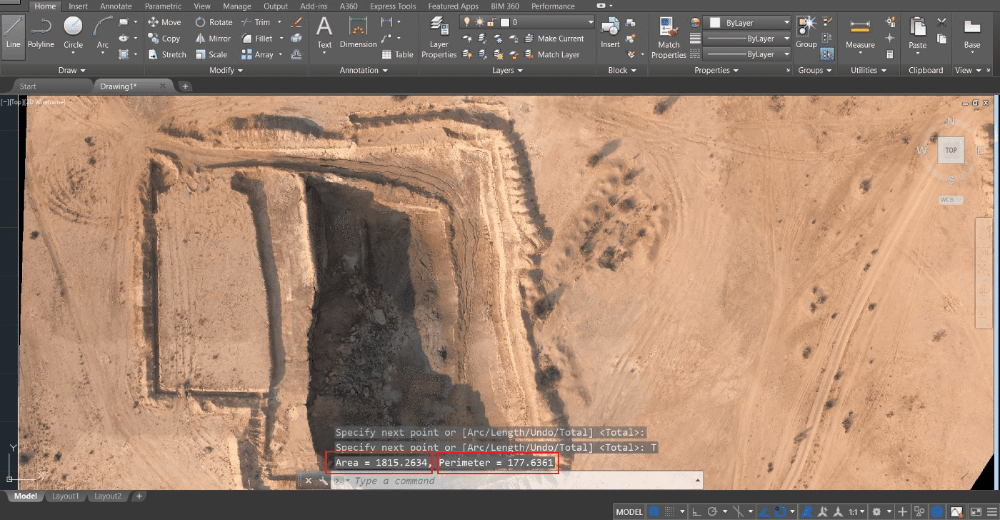
Perimeter and Area: Type AA command and select multiple points on the land. Once you have completed selecting the points, type T in the command box and you’ll get the Area and Perimeter as shown below.
Final Notes
Final Notes
We hope that you have learned how to import orthomosaic and perform basic measurements in AutoCAD. If there is anything that you guys would like to add to this article, feel free to leave a message! Share this if you have liked it! Thanks!